
XL-3D -480V SCHEMATIC DIAGRAM
Consider Phase B in the XL 480V 3-Phase 3-Wire circuit schematic in Figure 1 below.
- When phase C and A are magnetically induced in phase B, the resulting amperage appears as a 60 cycle wave form with a 120 degree cycle amperage superimposed.
- Since the amperage is negative its 180 degrees out of sync with main phase amperage.
- Therefore, the power generating transformer action of XL Chokes have the net result of reducing total amperage at the source (billing meter) and since it’s a leading amperage, reduces inductive VAR.
 Color coded schematic diagram of an XL 480V 3-Phase 3-Wire module. See color coded component schedule below which helps to explain the schematic diagram.
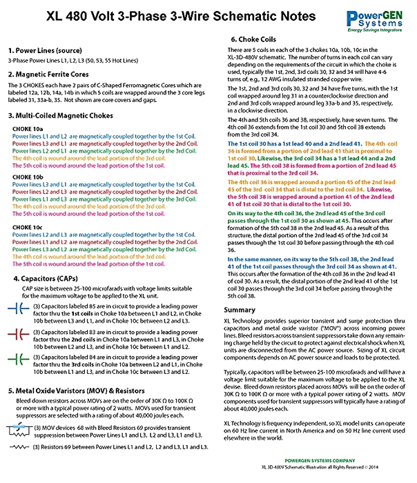 Color coded schematic notes for the XL 480V 3-Phase 3-Wire schematic diagram above.