
XL SYSTEMS DECREASE FACILITY MAINTENANCE COSTS
 Figure 1: Facility equipment maintenance record keeping.
XL System customers with accurate maintenance records have verified a decrease in equipment maintenance cost which in turn can decrease equipment downtime.
Facility maintenance cost savings are largely due to inductive equipment loads operating more efficiently due to improved power quality throughout the facility.
It has been verified in maintenance records that motors that operate more efficiently saw reductions in costly pre-mature re-builds and replacement. This in turn can decrease equipmwent downtime due by reducing scheduled and unscheduled equipment maintenance.
Inductive motors are inherently inefficient ...
 Figure 2: Mechanical room
By reducing Apparent Power (KVA), improving Power Factor and eliminating high in-rush Amperages associated with the starting of induction motors, XL customers have realized maintenance cost savings on motors and other equipment by reducing repairs, premature replacement and scheduled and unscheduled downtime.
Furthermore, by reducing Amperage and Apparent Power (KVA), but not motor rpm, XL Systems have been proven to reduce motor stress and improve motor cooling which results in lower maintenance costs and fewer breakdowns.
 Figure 2: Total Power Loss Graph
Motor Efficiency: Electrical motor efficiency is the ratio between the shaft output power - and the electrical input power.
If power output is measured in Watt (W), efficiency can be expressed as:
ηm = Pout / Pin
where
ηm = motor efficiency
Pout = shaft power out (Watt, W)
Pin = electric power in to the motor (Watt, W)
Static Loads result in very high starting currents; motors demand the right amount of energy or real power (Watts) to overcome their stationary loads - motors are built to deal with this stationary load. Induction motors also run at a constant speed, almost irrespective of load. Once started and the motor has gained full speed, the current (amps) drawn from the supply usually falls. However, this 'running' level of current is typically still too high and the energy is manifested as heat, vibration and noise as well as the movement of the load which is "Wasted Energy".
Inefficiencies of electrical induction motors are characterized by the following losses which add up to give the total power loss shown in Figure 2.
- Iron Losses
- Copper Losses
- Friction Losses
- Stray Load Losses
Iron losses (Fe) also called the magnetizing losses - these are voltage related and therefore are constant for any given load. The magnetizing losses are comprised of the hysteresis losses and the eddy current losses. The magnitude of these losses is determined by the constriction of the motor and the type of steel. At low load, Fe losses predominate and produce the poor power factor.
Copper losses are also called the I²R losses and are proportional to the square of the load current. Copper loss is the generic term to describe energy losses that occur in any conductor (windings, in the case of transformers and other machines). The term applies, even when the conductors are manufactured from aluminum or other metals. The losses occur due to the temperature difference between the conductor and the surrounds, causing heat transfer away from the conductor.
Frictional losses are also called mechanical losses - bearings, windings, windage. Mechanical losses also include friction in the motor bearings and the fan for air cooling.
Stray load losses are caused by disturbances of the magnetic field due to the change in load. Stray losses are the losses that remain after primary copper and secondary losses, iron losses and mechanical losses. The largest contribution to the stray losses is harmonic energy generated when the motor operates under load. These energies are dissipated as currents in the copper windings, harmonic flux components in the iron parts, leakage in the laminate core.
XL Systems Increase the Operational Efficiency and Longevity of Inductive Loads, Particularly Motors and Transformers
 Figure 3: XL Systems Expands Motor Life & Reduce Production Downtime.
Amperage Reduction - XL Systems reduce Real Power Demand (KW) through amperage reductions on load circuits, which reduce "Copper Losses", and through the reduction of Total Harmonic Distortion (THD) in the amperage and voltage supplied to operating loads, which improves motor efficiency, expands motor life and reduces maintenance costs and downtime.
Reactive Power (KAVR) Reduction - XL System modules can reduce up to 44,000 VAR or 44KVAR of Reactive Power depending on the module model. A reduction in Reactive Power (KVAR) results in a corresponding decrease in Apparent Power (VA) on the circuit. This, in turn, results in a decrease in the amount of amperage on the circuit, which results in a decrease in Real Power Demand (KW) as a result of reduced "Copper Losses" on the circuit.
Copper loss Reduction - Copper loss is a power loss due to current flowing through wire. Copper losses manifest themselves as heat in motors and conductors and can reduce the useful life of motors, transformers and sensitive electronic equipment. The reduction in Reactive Power (KVAR) on load circuits also acts to “stiffen” the circuit by reducing overall circuit impedance. A “stiff” circuit will reduce the creation of Voltage Total Harmonic Distortion (VTHD) as a result of current harmonics.
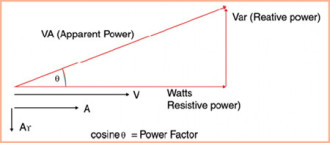 Figure 4: The Power Triangle
Power factor (PF) is the cosine of the angle between resistive or Real Power (Watts) and Apparent Power (VA). The ideal PF is unity or 1.0, however in inductive motors PF is less than unity and is typically in the .75 to .85 range. PF is an issue when Reactive Power (VAR) exists which is caused when Voltage and Current are out of phase.
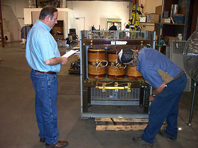 Figure 5: XL Systems Reduce Transformer Maintenance and Increase Capacity of Electrical Systems and Gear
Voltage Regulation – XL Systems improves and regulates voltage across each of the three inter-phases (VAB, VBC, and VCA) thru magnetic-phase coupling which reduces circuit amperage and helps motors run cooler and last longer.
Increased voltage also lessens the likelihood of equipment tripping off due to utility voltage sags.
Fluctuations in voltage are dampened by the coupling of the three inter-phases of power supplied, which also lessens any likelihood of equipment tripping problems associated with voltage fluctuations.
 Figure 6: XL Systems relieve electrical stresses in transformers; this ultimately increases capacity and extends longevity.
Phase Balancing – XL System modules employ Magnetic Phase Coupling circuitry which is a power conditioning mechanism where conductor amperage and voltage transients are balanced between the phases in each conductor as well as the phases in other coupled conductors.
Thereby relieving electrical stresses, increasing the efficiency and reducing the harmonics of three phase motors and transformers.