Technical Overview
On the basis of the magnetic fields sensed, a signal is generated that enhances the AC wave form and matches it to the requirements of the load. The peak portion of the current wave on the line side is decreased and electrical system inefficiencies originating in the supplying transformer are reduced.
USES® XL Systems reduce electrical energy waste by:
- matching voltage and current phases in inductive systems;
- reducing harmonics, spikes and noise;
- reducing I2R losses;
- balancing loads across all phases.
USES® XL Systems consist of maintenance-free modules installed in parallel to existing electrical systems. These Systems can be connected centrally to Main Distribution Panels (MDP) located at
utility service entrances or they can be distributed and connected to subpanels located closer to loads, they can also be connected to VFD's, Adjustable Speed Drives (ASD) or directly to loads on the
controller side of the load.
USES® Patented Circuitry
The Schematic diagram in Figure 1 below is an example of the New USES® XL-3D-480V power conditioner installed on an AC source having three hot lines 50 (L1), 53 (L2) and 55 (L3). Three chokes 10 a, 10 b and 10 c are provided, each having the same configuration of the New XL multi-coil choke 10 shown in Figure 2 below. The first, second and third coils 30, 32 and 34 of each choke are coupled to lines L1, L2 and L3 of the power source as shown. Additional components in this implementation include lamp 80 and series resistor 81, and capacitors 83, 84 and 85. An additional bleed resistor 69 is also provided across varistor 68.
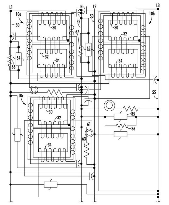 Figure 1: Schematic Diagram of USES XL-3D-480V Power Conditioner
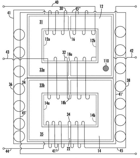 Figure 1: The New and Improved XL Multi Choke Coil Technology
The multi-coil choke contained in the USES® XL technology provides power conditioners with improved transient and surge protection as well as substantial energy savings over prior power conditioners, including significant improvements over the USES® CMES power conditioners.
Transient and surge protection is provided by the various capacitors and transient suppressors. As shown in Figure 1, capacitors are provided across power lines. Transient suppressors, such as metal oxide varistor ("MOV") devices can be placed at various points throughout the circuit. An MOV can be placed across incoming power lines. An MOV can be coupled from incoming lines to neutral. MOVs can be placed between neutral and ground. Bleed resistors across the transient suppressors take down the charge held by the circuit to protect against electrical shock when the unit is disconnected from the AC power source.
The values of the various components shown will depend upon the AC power source to be conditioned and the loads to be protected by USES® power conditioners. Typically, the capacitors will be between 25-100 microfarads and will have a voltage limit that is suitable for the maximum voltage to be applied to USES® power conditioners. The bleed down resistors placed across the varistors will be on the order of 30K Ω to 100K Ω or more with a typical power rating of 2 watts. The MOV devices used for the transient suppressors will typically be selected to have a rating of about 40,000 joules each.
USES® power conditioners using the multi-coil chokes disclosed in Figurre 2 above are frequency independent, so that they can work on both 60 Hz line current found in North America as well as on 50 Hz current used elsewhere in the world. USES® XL Power conditioners manufactured using the new inventive XL multi-coil chokes are vastly improved over prior USES® CMES power conditioners due to various factors, including the three leg core design, the provision of five coils in each choke with the winding configuration taught herein, and the four separate air gaps provided in the core. These air gaps are shown most clearly in Figure 1 as gaps 16, 18 (18 a and 18 b), 22 and 24. Tests have shown that energy savings are about double the savings provided by prior USES® CMES power conditioners, with faster surge suppression and the ability to handle larger surges. The improvements in surge suppression are achieved, at least in part, due to the multiple air gaps provided in the chokes which prevent the chokes from saturating. Better filtering is also provided by USES® XL power conditioners using the chokes.
The components of the USES® power conditioner can be provided in a module that is connected to a user's power lines at the service panel. Alternatively, the module can be connected to the user's power lines at a load. A plurality of such modules can be provided throughout a commercial facility. For example, one module can be installed at each fluorescent light fixture in an office building or on each separate line feeding such lighting fixtures. Connections to the module are made at taps on the power lines. There is no need to cut the power lines when installing the module, since none of the components are placed in series with any of the lines.